|
FCST01143
FCST
FCST01143
Product Features
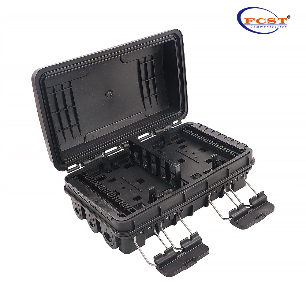
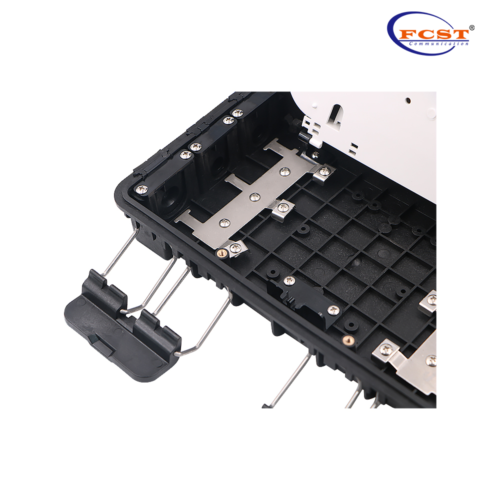
l The fiber closure is made of high-quality impact resistant plastic and has a standard user interface that can be re-opened. Can accommodate two 1x8 PLC splitter LGX module or steel tube type;
l Anti-ultraviolet,anti- impact and waterproof function;
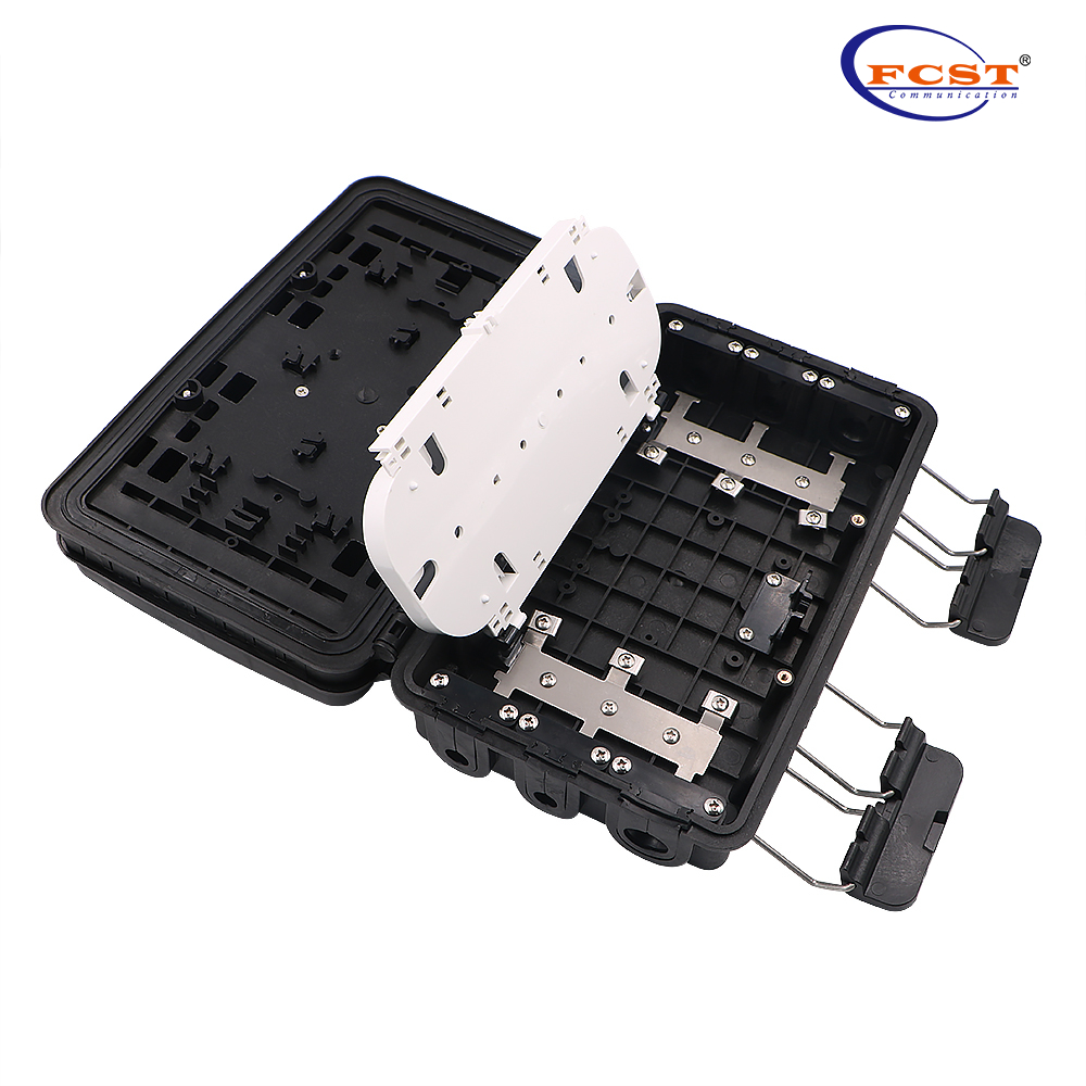
l Unique flip board, flip angle ≥ 180 °, fusion area and distribution area is more obvious, reducing the cable crossing;
l Fiber optic cable can go in and out of the box without cut the cable.
Product Specifications
Model | FCST01143 |
Dimension (mm) | 285*175*110 |
Cable Diameter (mm) | Φ 7-φ 18 |
Cable Port | 2pcs 8-20mm round ports,4pcs 5-16mm round cable, 16pcs 3-7mm drop cable ports |
Max.Split Ratio | 2pcs 1x8 steel tube splitter |
Max. Adapter Number | 18pcs |
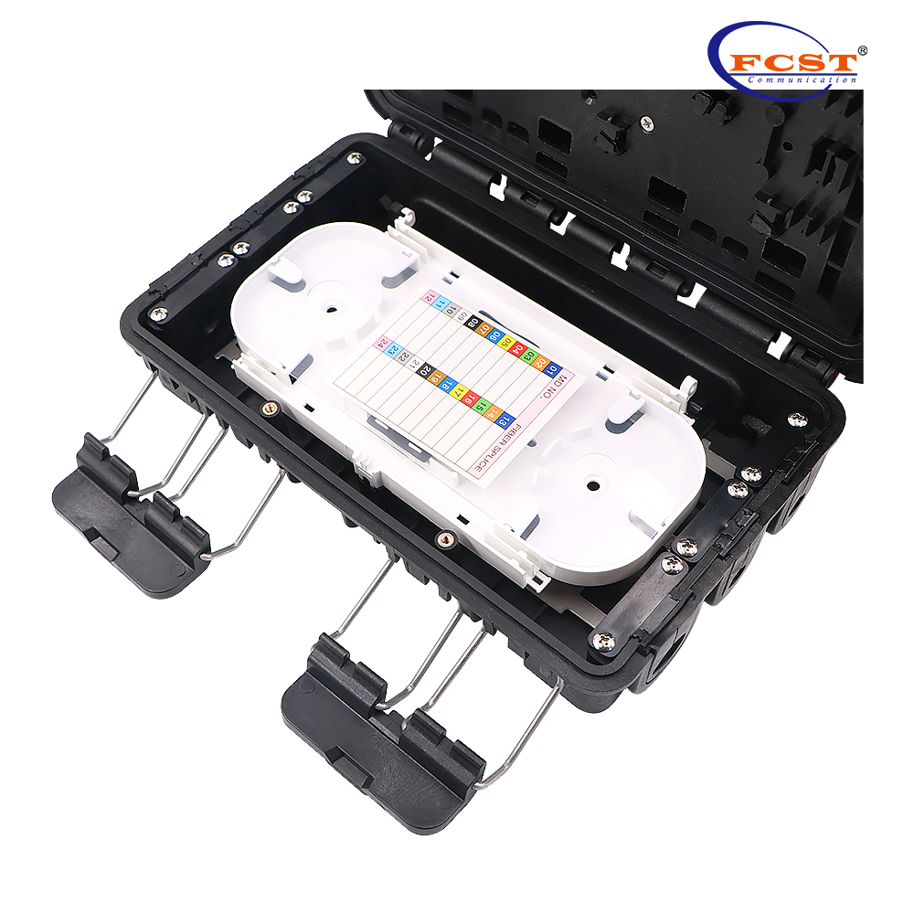
Max. Splice Tray | 1pc |
Max. Fusion Splice | 24 cores |
Technical Parameters
l Optical fiber radius of curvature:≥40mm.
l Splice tray additional loss: ≤0.1dB .
l Temperature range: -40°C ~ +60°C.
l Anti side pressure: ≥2000N/10cm Impact resistance:
≥20N.m Protection class: IP65.
Installation Procedure
Open box, install the adapters on the plastic holder. (See fig. 1)
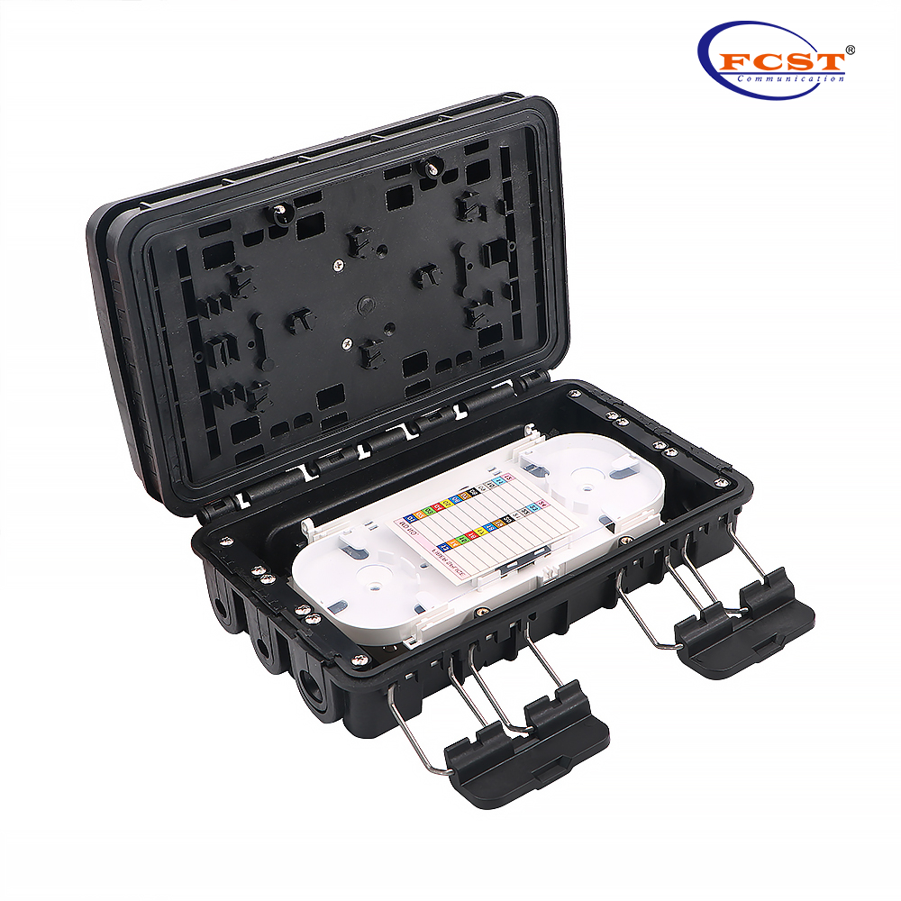
Strip the outer jacket,inner jacket, loose tube off the cable, remove the oil filling paste inside the cable, keep the fiber length of 1-1.6m and the steel core of 30-50mm; insert feeder cable through the entry and lock with hoop, strength plate to fix the fiber core. The excess optical cable is coiled at the bottom, and the fused fiber optic cable is introduced into the fiber tray. Superfluous optical fiber cable will be fixed and stored at the bottom of the box, bring the cable into the splice tray. (See fig. 2)

Insert the drop cable connectors into the splitter module adapter (output side), then fix the cable into the fixing slots, then through the rubber seal to lead out the cable. (See. Fig. 3)
Insert the cable pigtail into the fixing slot, and then pass through the outlet sealing rubber to lead out the cable.
Close the lid,snap the buckle to complete the installation,install the metal hooks then hook up on the aerial cable.

Design And Customization Services
l The fiber optic splice enclosure rovide service with whole process from blueprint to product to the customer.
l Meet customer’s requirement to customize logo in suitable place for existing product.
l Meet customer’s requirement to make reasonable modify and customization for existing product.
l Provide free design according to the requirement of customer after signed cooperative agreement.